
In this part, we will talk about our development model views described in Unified Modelling Language. UML is a language which we will apply to describe use cases meaning the interactions of an actor (user) and a system to achieve certain goals. This is an in-between process: after we gathered all requirements and shaped our agenda and before we actually started coding.
Our app users
In previous posts, we identified our user personas. Now we can proceed and implement those personas into our interaction use cases. It helps us to identify the functionalities we want to offer to them. We don’t have to cover now the scenario of a registered or authenticated user, but we will treat as a seperate diagram.
Our app functionalities
Now we identify general functional blocks we offer for the actors (personas) aligned with activities they perform.
The First Persona is identified as a novice who comes for social value and expert advice. is clearly interested in
The Second Persona is an expert who was a novice at the beginning, but after a certain amount of contribution (posts, advice, photos etc.) became an expert (high degree of centrality) and can provide help/advice/guidance to novices.
Finally, the Third Persona is a commercial partner type of user who is interested in business add-on value.
Three iterations are needed to reach the outlined use case scope.
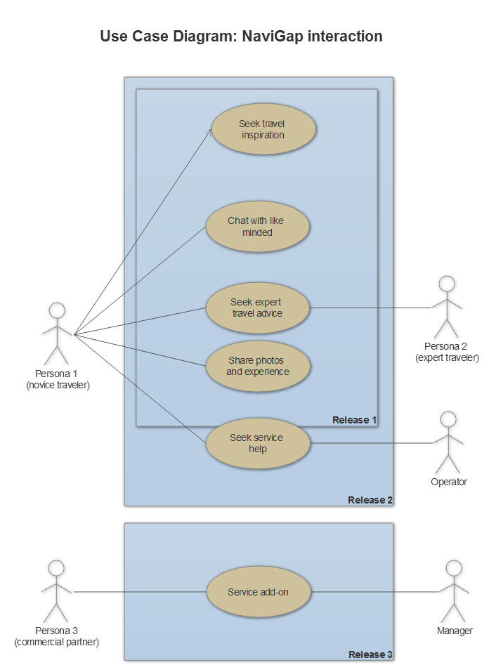
Figure 1. Use Case Diagram: NaviGap interaction
At this point, we can augment the Persona 1 case by expanding each functionality. For example, ‘Seek travel inspiration’ functionality:
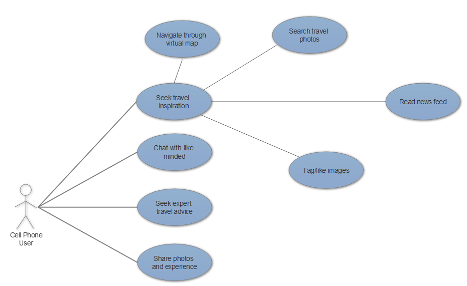
Figure 2. Use Case Diagram: Augmented functionality
Through each augmentation iteration, we ask ourselves: is it enough? have we listed all possible functionalities that we can release? Step by step we will augment our UML layout and add blocks to each functionality. After each functionality has a detailed list of sub-functionalities we can look at it critically and think of additional features that will give us a competitive edge.
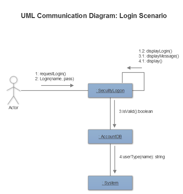
Our app communication diagram
As an example of UML communication diagram, we show the scenario when a user wants to login into their account. That provides a model-view-controller perspective of interaction.
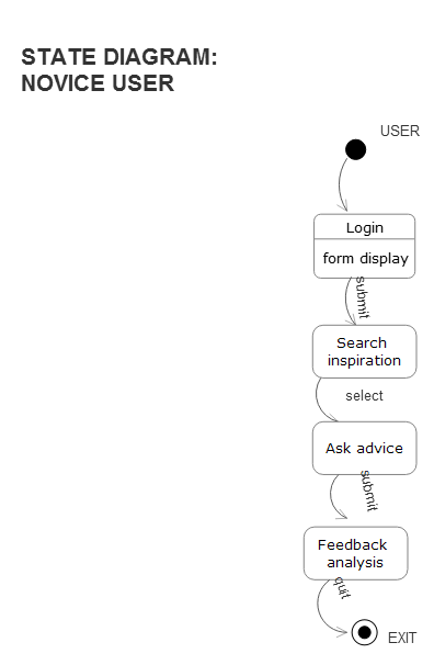
Our app state diagram
State diagrams can be seen as the essence of object-oriented programming (OOP). Those diagrams are good when we want to describe the behavior of a single object. In general, those diagrams define various states of an object during its life cycle.
A state diagram represents the actual changes in state, not the particular processes/commands creating those changes.
Why we need all those diagrams?
We assume that our team should have a clear understanding how the users interact with the App, what functionalities we are planning to offer to them and in what way they can access them. Overall, each diagram builds up a clear understanding of what is expected from the app, what role the users and other actors play in it, and helps to shape the outline of the UI design.