We finished our power subsystem printed circuit board (PCB)! It’s the first complete piece of UoS3 electronics that we made in-house, so it’s a big moment for us. This board houses all the components that take part in distributing the power on board the satellite. This is to say this board gathers the energy from the solar panels. It then conditions it to the right voltage (we use primarily the standard voltages of 3.3 and 5.0 V) and distributes to all the satellite loads. The excess power is stored in a battery; when the satellite is flying through Earth’s shadow the on-board components are running off the battery because the solar panels aren’t generating any power. Should any loads on-board UoS3 malfunction and draw too much current or burn out, this PCB will also ensure that this failure doesn’t affect the rest of the satellite.
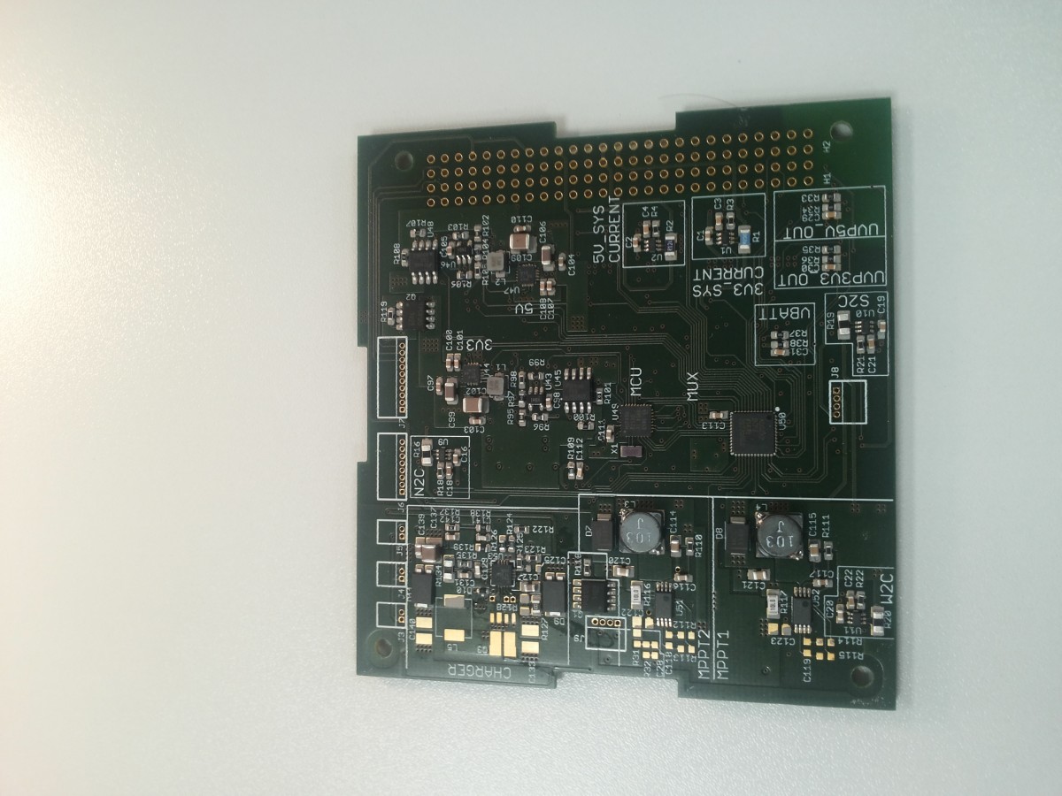
This printed circuit board (PCB) houses components that make sure we get as much energy from the solar panels as possible. It also enables us to draw power from a battery when the satellite is flying through Earth’s shadow. And lots more functions that are too many to list!
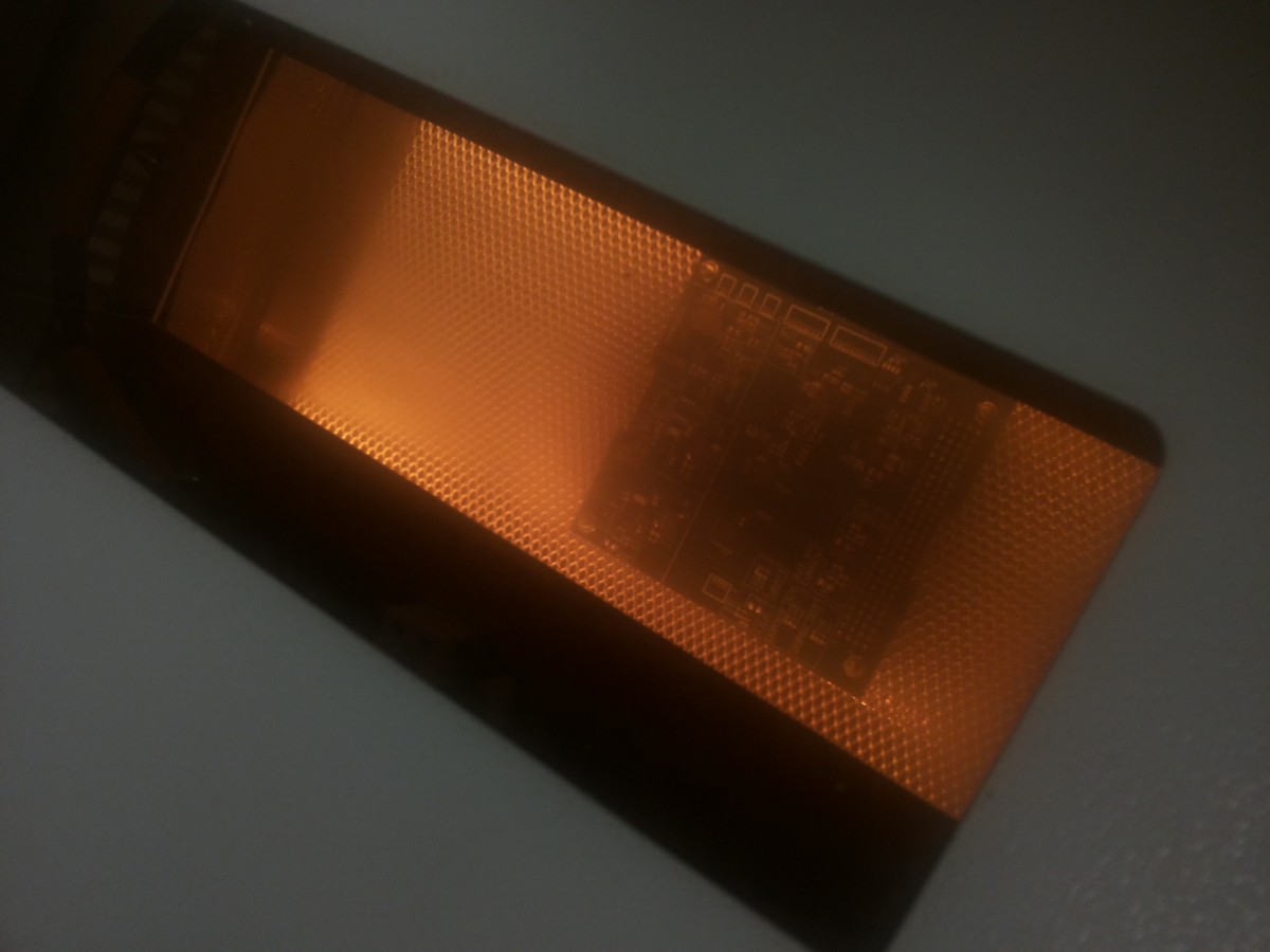
The manufacturing process was rather involved. First, we had PCB substrates made; this is no simple tasks and is normally handled by specialised companies. But we did all the rest. We covered the PCB substrate with solder paste and manually placed all the components, for example chips and resistors, in the correct locations on the PCB. There were many of them so we had to be careful to be sure we haven’t forgotten anything.

We methodically placed all the components on the PCB and ticked them off the list to make sure we didn’t forget anything.
Then we placed the PCB, with components on it, in an oven and baked it for a while. The solder paste melted and joined the components with the PCB. Typically, spacecraft are hand soldered. However, this is a very lengthy process that requires a lot of training and experience. We decided that it was safer to solder all the components using an oven and not rely on individual’s soldering skills. The net result is a nice PCB that works, so we’re happy with the process that we followed.
We soldered most of the components onto the power subsystem PCB in an oven to ensure they are well bonded with the PCB substrate. Most spacecraft are hand-soldered, but this is a very long process which we aren’t experienced at, so this was a better solution.
No comments yet.