Getting Ready for 3D World
This learning object explains the basics of aerial imaging, viewing perspectives, cameras and stereoscopic viewing. The material also helps the reader to check their 3D viewing capabilities using test stereo patterns.
In photogrammetry, a few terms and concepts are regularly used. These include camera, scale, flying height, focal length, view angle, stereoscape, resolution, and parallax etc. We here begin to introduce these different concepts.
Camera
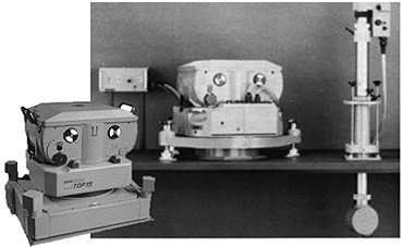
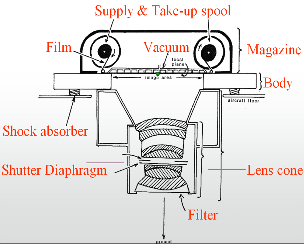
Aerial cameras are geometrically accurate and sensitive enough to capture very small features [with higher dots per inch (DPI)]. The following picture depicts an aerial camera and the various components of an aerial camera system.
Focal length
The focal length of the camera refers to the length at which the lens can form a clear image of the incident lights. (i.e., distance between the lens and the film). This is the distance over which the optical system is able to bring collimated (parallel) light rays to focus at a point.
Camera Perspective
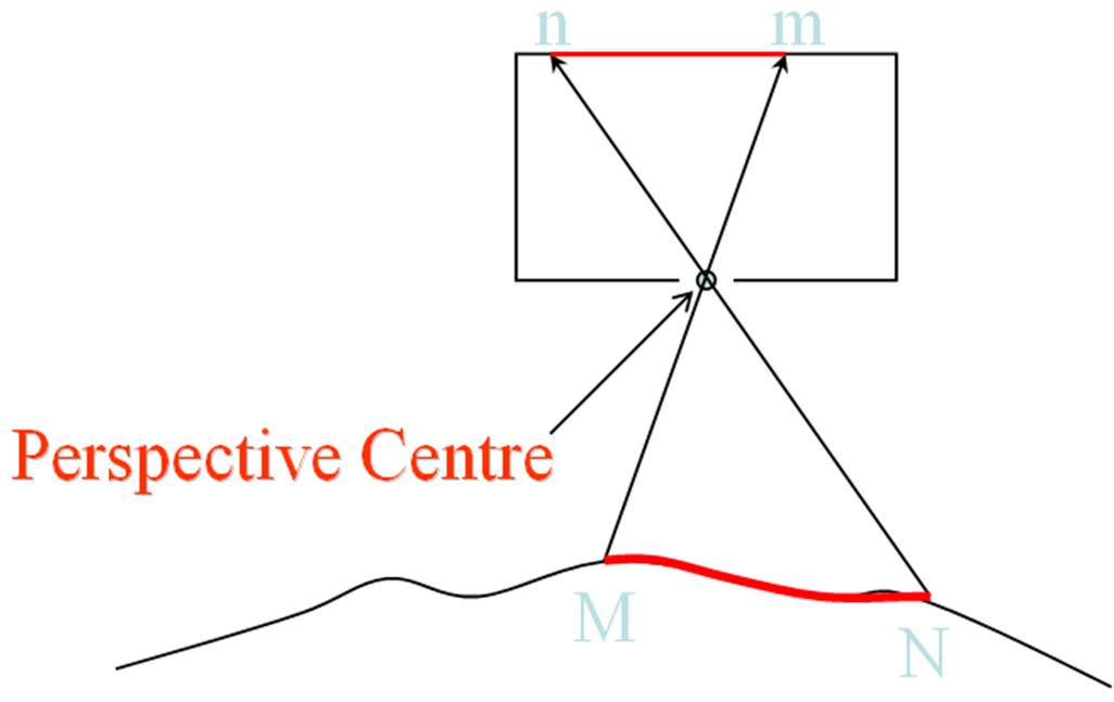
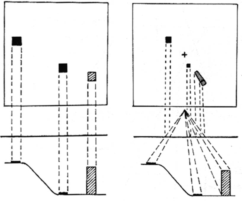
The image captured by the aerial camera has a few distortions, which are normally not seen in maps (i.e. traditional topographic sheets (toposheet) prepared by national mapping organisations). This is due to camera perspective. Toposheet maps are prepared based on orthoganal viewing, in which light rays are projected vertically upwards from each point on the ground, whereas in the camera system the light rays converge through the camera lens. The following pictures explain these perspectives. The first picture shows how the camera perspective views the ground. The second picture depicts the orthogonal aspect of toposheet maps, and the third picture shows the central perspective aspect of the camera.
Reflection
In the last image, the tall building is depicted as leaning outwards from the centre. Can you understand this mysterious behaviour? What will happen to the structures which are below the normal ground level?
The height of an object introduces displacement in the image, which is called relief displacement. The underground features will lean inward (towards the centre of the image).
Incorrect
Scale
The scale of an aerial photograph depends on two important things: focal Length (f) and flying height (H).
The focal length of the camera is known, and flying height is also nearly fixed – but will be variable during flight due to wind and other factors. The flying height is normally measured from the datum (i.e. mean sea level).
Photo scale = (photo distance / ground distance)
Reflection
Suppose you are given an aerial photo and asked to measure the scale of the photo, then how will you estimate it? The problem is how do you know the ground distance without knowing the characteristics of the study area?
In such cases where the user does not have any knowledge of the area captured, they have to use some standard features such as widths of major roads, width of a railway track or size of a car, etc.
Incorrect
Another way to calculate the scale is as follows:
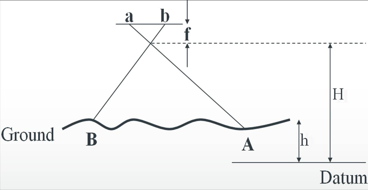
Scale = (focal length / flying height above the ground) = f/ (H-h)
This equation is arrived at by using the law of similar triangles.
Another problem in measuring scale is that scale is not constant within the aerial photo. This is because the flying height is not constant. We will need to learn how to remove such varying scale distortions.
Activity – Scale Calculation Exercise
a) If the photo distance ab = 193.4mm, and corresponding ground distance AB = 3868 m, calculate the scale of the photo.
b) The aircraft is flying at height 3.34Km, and the minimum ground height recorded in the study area is 100m and the maximum height is 500m. Assume the focal length of the camera is 15.2cm. Calculate the scale of the image.
Activity – 3D Vision
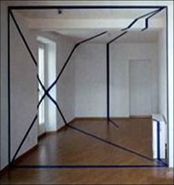
The way our eyes view and our brains interpret 3D objects can be peculiar. Consider the image below: what do you see? Most people will see a 3D structure cutting across the room. But actually this is not the case. Click below to see the room from a different angle.
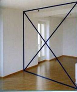
The 3D structure is created by our brains. Here, the lines have been drawn across the walls, ceiliing and windows of the room.
Incorrect
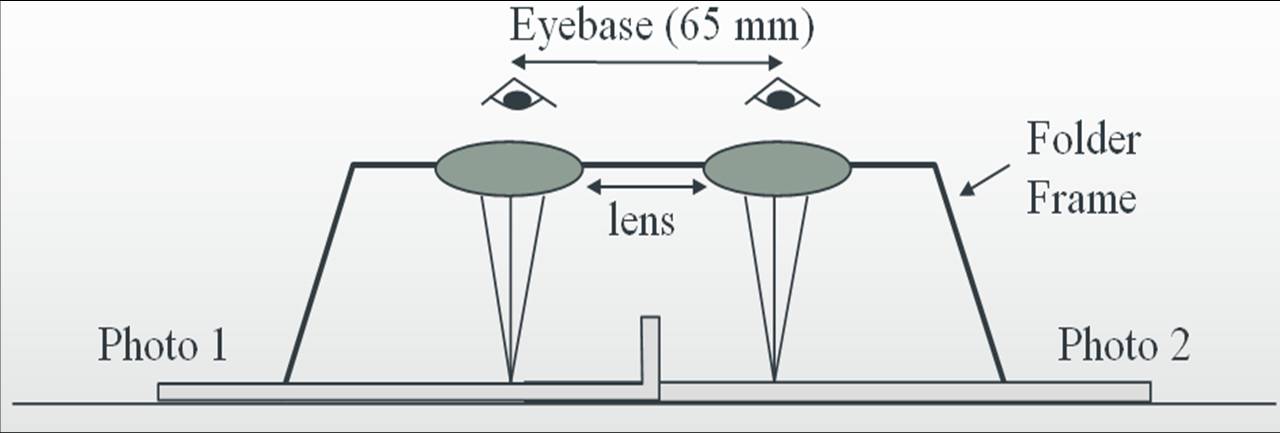
Stereoscope
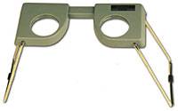
In photogrammetry a good 3D vision is very important. Our eyes acts as two cameras, each one capturing different areas of space, and there is an overlap between these two images captured by the eyes. These two frames of images are seen and interpreted by our brains as a 3D space. The optical instrument which helps in creating a similar 3D space is called a stereoscope. There are two types: the pocket stereoscope and the mirror stereoscope. A pocket Stereoscope and its viewing geometry looks like this:
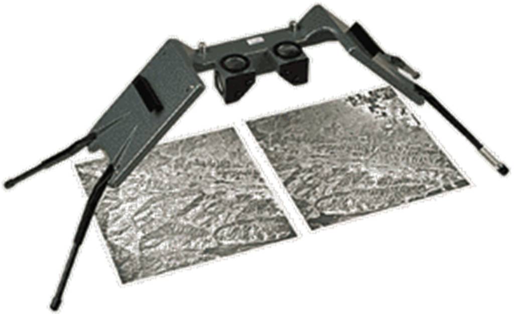
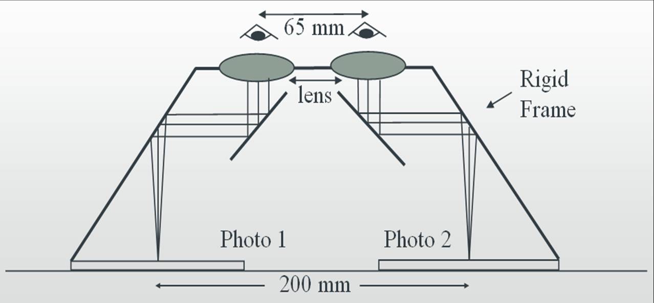
A mirror Stereoscope and its viewing geometry looks like this:
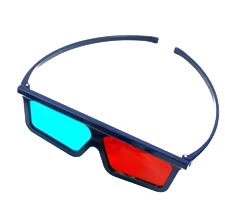
3D Vision using Anaglyph Glasses
3D viewing is also possible using anaglyph glasses. Anaglyph glasses have coloured lenses instead of transparent lenses. Different colours, most commonly red on the left and blue/cyan on the right, are used. The glasses look like this:
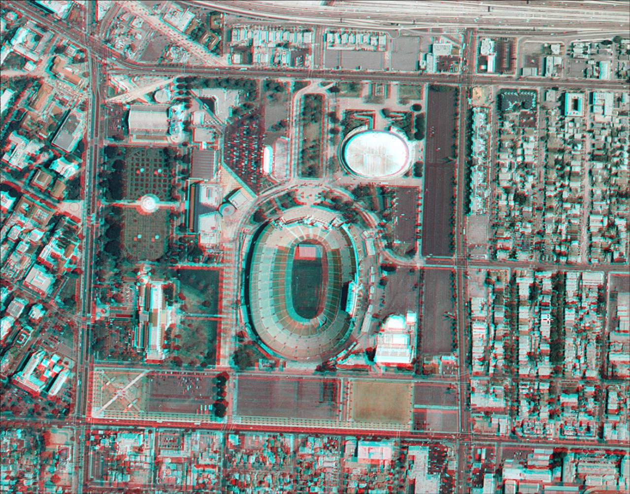
Two images, one for the left eye and another for the right eye, are required to create a 3D viewable image. These two images are passed on to red and cyan display mode in the computer and then superimposed in such a way that each eyepiece of the angalyph glasses only see one coloured image allowing the brain to form a 3D image. The following aerial image taken over Los Angeles was created in Erdas/Imagine Stereo Analyst software. Anaglyph glasses will be required to complete the following section.
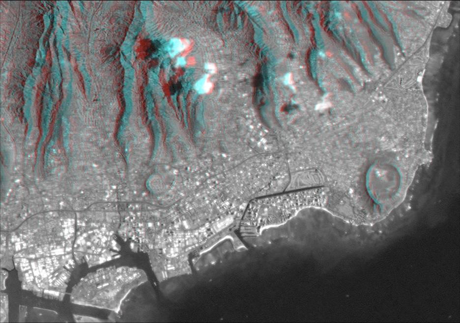
The second image is from Hawaii
Activity – 3D Vision Testing
It is important to understand the 3D viewing ability of our brains. For some people it is very difficult to see 3D on screen. The test below will help you understand your ability. Have a look at the picture. For this you need an anaglyph glass. Let your eyes relax for a moment. Try to arrange the circles from top to bottom - i.e. the one appearing closest to you to the one appearing furthest away. It is generally easy to find the topmost, but the depth difference decreases when you move further down, you need a very careful eye to successfully interpret the much smaller differences in their heights. Click below for the correct order of arrangement.
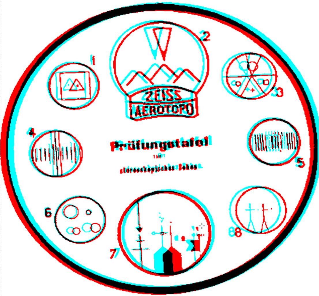
The order of arrangement is 7,6,5,1,4,2,3,8.
Incorrect