Recent Comments
Archives
Categories
- No categories
Meta
5.1. Types of Sensor
Objectives
This learning object provides an overview of types of sensor used in remote sensing. It explains the basic principles of their operation. Sensors detect the amount of energy reflected/emitted from the Earth surface and thereby provide information about its characteristics.
Most remote sensing instruments (sensors) are designed to measure photons. Fundamental to this operation is a device known as a detector which works to measure radiation (a beam of photons) on the basis of the photo-electric effect. When a light-sensitive material is subject to a beam of photons, electrical energy is released and this energy is proportional to the amount of incoming radiation. A sensor thus provides a means of measuring radiation. This basic mode of operation is common to each of the sensors considered here.
Active and Passive Sensors
Fundamentally, there are two types of sensor depending on the source of energy. Active sensors provide their own energy source for illumination. This means that measurements can be obtained at any time, regardless of the time of day or season. Such sensors may also allow examination of wavelengths that are not sufficiently provided by the sun (microwaves) and also provide better control of the way that a target is illuminated.
Passive sensors, by contrast, measure energy that is naturally available. They therefore are constrained by a requirement for sunlight or radiation emission from ground objects and offer limited control over the way that a target is illuminated.
Imaging and Non-imaging Sensors
Another distinction is between imaging and non-imaging sensors. A non-imaging sensor measures the radiation received from all points in the sensed target, integrates this and registers a single response value, hence no image can be made from the data. This may be considered a type of “point” data as only a single value is obtained for a single observation point. A hand-held doppler radar used by police forces to measure the speed of a vehicle is an example of an active, non-imaging sensor: it emits pulses of radiation (i.e. provides an energy source) and the readout is simply the speed of the vehicle (i.e. there is no image).
Imaging sensors measure radiation at different points on the target and this information can be processed in order to obtain an image. This is necessary when spatial information about the target is needed, in the form of a map.
Some Scanning Terminology
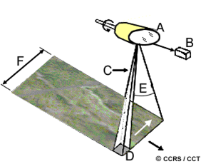
(Image source: Canada Centre for Remote Sensing)
The detector – B operates through a rotating scan mirror – A
The field of view (FOV) is the total angle measured by the instrument in one scan – E
The instantaneous Filed of View (IFOV) is the solid angle extending from a detector to the area on the ground it measures at any instant – C
The ground resolution element (GRE) is the area measured by the sensor for each IFOV (broadly equivalent to the pixel) – D
Swath is the width of the area measured – F
The size of GRE is a function of IFOV and altitude of the platform, while the swath width depends on FOV
Scanning Systems
A further characteristic of sensor systems is the operation of scanning, whereby a sensor with a narrow IFOV is swept across the terrain in order to build up a series of readings for different locations. Scanning can be undertaken either from airborne or spaceborne platforms (aircraft or satellites). Two principal mechanisms are employed to produce the scanning motion of the sensor:
Across track (whiskbroom) scanning sensor
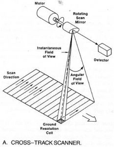
(Image source: Canada Centre for Remote Sensing)
In this arrangement, scanning lines are perpendicular to the direction of movement of the sensor platform. The sensor is usually an optical-mechanical device which operates by use of a rotating or oscillating mirror, focusing radiation from different points on the target surface into the detector as it spins. The components are:
1. a light gathering telescope
2. appropriate optics (e.g. a lens) within the light path
3. a mirror, which usually oscillates over small angles
4. a device (spectroscope) to break the incoming radiation into spectral intervals
5. a means to direct the light so dispersed onto a battery or bank of detectors
6. other electronics to store data
Along track (pushbroom) sensor
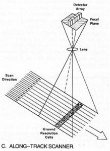
(Image source: Canada Centre for Remote Sensing)
This is an alternative configuration, whereby scanning lines are oriented parallel to the direction of motion of the sensor platform. Instead of a mirror there is an array of small sensitive detectors stacked side by side, each of which is a charge-coupled device (CCD). Each element in this detector array records data from a unique ground resolution element, hence multiple observations are recorded at the same time. Different sensors in the array may record radiation in differing wavebands relating to the same GRE.
Activity
This exercise may be carried out on paper but could also be enhanced by a little practical experimentation with a digital camera or mobile phone: it is not necessary to take more than one or two photographs in order to establish the necessary parameters!
Consider an area of ground with which you are familiar and which is accessible to you – perhaps a part of your garden, patio or balcony or a small area of a local park. Select an area which is approximately rectangular and make reasonable estimates of its length and width. Consider carefully how you could go about creating a photographic mosiac of the ground surface viewed from above using a simple photographic device such as a digital camera or mobile phone held at a comfortable height when standing on the ground. Ideally, take a photograph of something of known size in order to work out how large an area is represented by a single image (this may need some experimentation!) and then consider how you would set out an efficient plan to take successive images in order that when placed side-by-side in the correct orientation they would comprise a complete representation of the ground surface.
Consider the basic terminology and parameters introduced above and try to identify the equivalent parameters for your garden photography exercise. What are your IFOV, GRE and swath values? Can you see how the exercise could provide parallels to the operation of a whiskbroom or pushbroom scanner?
Show Answer